Colorado!

I just returned to school last week after spending 3 weeks in Colorado. Helen's grandmother has a ranch out there. The ranch is aging a bit; the house hasn't seen much maintainance recently. Helen and I made a habit of recording the things we fixed. Although it's incomplete and terse compared to my usual writeups, the list is reproduced below, for archival sake.

  • Removed broken window by the chicken coop
  • Repaired coop latch so the door closes easily
  • Replaced broken F350 taillight cover and bulbs
  • Partially pushed out a dent in the truck
  • Slightly improved on the hay hoist we built last year
  • Installed an electric winch to supplement the manual hoist

Lafbot Breakout

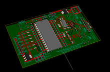
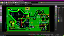
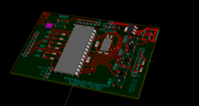
3d view of the PCB
KiCad offers 3d views. I think it looks pretty neat, myself.

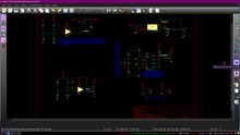
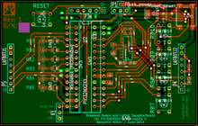
I'm pretty new to laying out circuit boards. My first use with any sort of schematic editor was two years ago - the college curriculum introduces some schematic capture software. I separately started learning KiCad when I made my little bicycle light. As you can see, it's pretty basic. My first real experience laying out a PCB came a few months ago, with my work on my solar charger (it's on hold until school starts up again).

I've been working at Lafayette over the summer. I'm focusing on the lab sections for Digital I and II, a two-semester series that introduce students to the digital abstraction, logic, programmable chips, and a bit more. I created labs for Digital I ranging from realizing simple logic using discrete gates to creating a game of Pong with an FPGA and a modern VGA screen. Right now, though, I want to talk about Digital II.

Lafayette just refactored its curriculum to introduce engineers to more in the liberal arts (the prior curriculum requred only 4 non-STEM courses in a students tenure). To add the social sciences, a few engineering classes were cut from the curriculum: Solid State Physics and Computer Organization are gone. The new Digital curriculum attempts to compensate for the loss of Computer Organization by accelerating both and adding course material on general-purpose computers.

Let there be cake!

The cake.
It's alive!

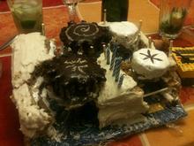
The cake.My girlfriend's birthday was a few weeks ago. Her 21st, to be exact. This was also the first birthday I'd be present for: she didn't celebrate anything the first year I knew her, the second year was in Germany, and this is the third year we've known each other. In the spirit of the occasion, I wanted to make sure she'd be happy with the party she had. 

Etching Away

This is a continuation of my work with a solar-powered USB charger. See the last article here.

A few days ago, I tried etching the board. It's nearly the first time I've etched anything at home, and it didn't quite work. (Etching, FYI, is the process of masking a copper board, dissolving the exposed copper with a reactive salt, and then removing the mask to reveal a printed circuit board.) Although the traces were beautiful, the entire board was mirrored vertically.

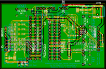
PCB layout for the power regulator The first etch wasn't a complete waste of copper, though. I found that my inductor footprint was twice the size it should have been (diameter != radius) and that the regulator's feedback was mistakenly connected to the switching supply, rather than the stabilized voltage by the capacitor. With that in mind, I trashed my original revision of the printed board and drafted one half the size. (The original had a lot of empty space.) I'm going to try etching again later today.

SunCell

All of my parts, arrayed across the table.
So much electronic loot.

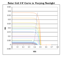
For years (and years), I've dreamed of making a little solar charger. You know, some little gizmo with a solar cell on one side, USB power on the other, and magic in the middle. That's always been the trouble, though: until recently, I didn't know enough magic electrical engineering to design one.

Now that I do, I'm a little surprised by how little the hard parts aligned with the parts I thought would be tough. The first time that I thought about this, back in high school, I was concerned about charging batteries. Everything else, I thought, would work off-the-shelf. Charging itself is the simplest part of the design.

So what was difficult? I'll get there. First, I want to talk about the parts I used and the design process.

E-Stop

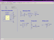
Original E-Stop Circuit
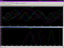
The LRC circuit, up top, runs the show.

You probably know I'm working on building an autonomous robot as a senior project by now. (Psst. If not, read about it. Here.)

Now, this robot is driven by a pair of horsepower motors. Given full throttle, it'll easily hit 30mph. Even with safeties baked into the autonav code and Arduino motor driver, we need emergency stops. In fact, we have three. One's implemented in the packet radio: we've defined a code that will immediately kill the robot. A button on the robot will cut power to the main relay. The third E-Stop is a hardware radio E-Stop. That's the most interesting one, and I'm going to talk a bit about how it's designed. And since you're such great listeners, you'll listen. Thanks!

The radio E-Stop comes has a few requirements. I'm going to put them in a list, since I just realized that breaking up text makes it easier to read. It must:

  1. not use any software (microcontrollers are presumably banned).
  2. have a range exceeding 100'.
  3. bring the robot to a "quick and complete stop".
  4. be held by the judges during competition.

Okay. The last 'requirement' isn't technical, but it requires the E-Stop to be portable. 

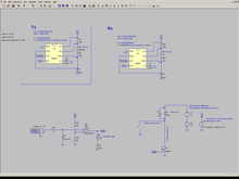
Given those requirements, I started putting together details about the e-stop. It needed a radio good to 100', so I found a cheap transmitter/receiver pair on Sparkfun. They're friendly in that they're easy to use, but that suggests a problem: what if someone else at the competition uses the same radio? We clearly needed some way to distinguish our E-stop from potential random noise. But it can't be too complicated; we're on a deadline and can't use software to distinguish long patterns. 

Base Station

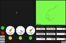
Over the past few weeks, I've been developing a base station for Optimus'. (That's the IGVC robot's name.) In order to operate autonomously, Optimus' is outfit with a slew of sensors. In order to keep tabs on Optimus' and his operation, the base station establishes a radio link with the robot. The robot constantly sends telemetry data out to the base station and the base station periodically sends commands to the robot. 

Coffee Table

I live in an off-campus house at college. It's a little thing: three beds, kitchen, dining room, living room. A sofa.

But no coffee table.

Not that anyone in my house drinks coffee, but we've wanted a knee-height table for the sofa for a while. Just to set drinks down on, or to use for homework. 

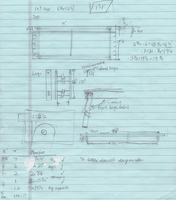
As long as I'm home, I decided to build one. As a design constraint, it's made entirely from 1x3 strapping. There is some reason for the choice. First, at $1.30 per 8' board, 1x3 is cheap. Second, the 1x3 theme matches a toolbox I built this summer. Third, it's cheap.

Divergence Mapping, Mark II

Mark II sounds technical. So is this post. In the last post, I described how divergence mapping works. Fundamentally, divergence mapping creates a 3d image using two cameras, much like the human eye. The link above goes into more detail on our high-level method; this post is about hardware.

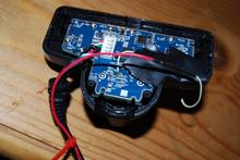
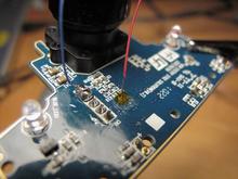
Here, you'll learn how to modify a PS3 eye for synchronized images. (Apologies, but I'm shy on pictures of the camera coming apart.)

First, remove all of the screws from the camera's backside. They're all hidden under the round rubber pads, which will pry off with a slotted screwdriver. The screws themselves are all Phillips. 

Next, gently pry the back off of the camera. The board and lens are attached to the front piece of plastic; the back will pull off. The two sides are attached with plastic hooks. I found that needling a slotted screwdriver between the layers of plastic and then twisting worked well. Start at the top, and save the round bottom for last (it's tough to get open).

Divergence Mapping

One of the most important sensors on the robot is a depth sensor, used to pick out obstacles blocking the robot. If the obstacles were uniform, color and pattern matching would suffice, but they're massively varied. The course includes garbage cans (tall, round, green or gray), traffic cones (short, cone, orange), construction barrels (tall, cylindrical, orange), and sawhorses (they look different from every side). Sophisticated computer vision could pick them out, but a depth sensor can easily separate foreground and background. 

Most teams use LIDAR. These expensive sensors send a ping of light and time the echo. Time is converted to distance, and the ping is swept 180 degrees around the robot. We can't afford LIDAR. Our depth-sensing solution is divergence mapping. The sensing works in much the same way as a human eye: two cameras, a small distance apart, capture images synchronously. The images are compared, and their small differences are used to find depth. People do it subconsciously; the computer searches for keypoints (features that it can identify between frames). The matching fails on uniform surfaces, but works well on textured ones. (Like grass; isn't that convenient?)
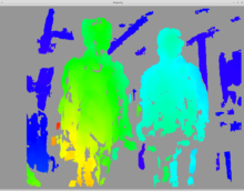
A depthmap visualized.The depthmap can only be generated when the images match closely. That means that the cameras need to be fixed relative to each other, and the images need to be taken simultaneously.
Pages