By Ben Nitkin on
I'm pretty new to laying out circuit boards. My first use with any sort of schematic editor was two years ago - the college curriculum introduces some schematic capture software. I separately started learning KiCad when I made my little bicycle light. As you can see, it's pretty basic. My first real experience laying out a PCB came a few months ago, with my work on my solar charger (it's on hold until school starts up again).
I've been working at Lafayette over the summer. I'm focusing on the lab sections for Digital I and II, a two-semester series that introduce students to the digital abstraction, logic, programmable chips, and a bit more. I created labs for Digital I ranging from realizing simple logic using discrete gates to creating a game of Pong with an FPGA and a modern VGA screen. Right now, though, I want to talk about Digital II.
Lafayette just refactored its curriculum to introduce engineers to more in the liberal arts (the prior curriculum requred only 4 non-STEM courses in a students tenure). To add the social sciences, a few engineering classes were cut from the curriculum: Solid State Physics and Computer Organization are gone. The new Digital curriculum attempts to compensate for the loss of Computer Organization by accelerating both and adding course material on general-purpose computers.
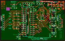
 In order to bring the new Digital II curriculum up to date with the modern age, I've been working on creating a microcontroller breakout board for use in Digital II. It's based on the PIC32 series, selected for its MIPS-based design. (MIPS is a simple pipelined computer organization that prioritizes uniformity, and simplicity, so makes an excellent learning platform.)
The department head further expressed interest in a board that would interface with the LAFBOT - a two-wheeled robot with light sensors designed for line following. The LAFBOT includes two eight-pin headers that read from the light sensors and can drive the motors. The batteries also provide power to the robot and daughterboard.
I figured that, as long as I was making a board, I might as well make it useful. In addition to strapping onto the LAFBOT, I thought of some things sophomore ECE's might put to good use and put them on the board:
- 2 dedicated analog inputs (buffered for low impedance)
- 6 digital input/output pins
- Serial and I2C communication
- Separate serial port to communicate with a robotic arm the school owns
- USB (hopefully for programming)
- 4 buttons
- 5 LED's
- Selectable power (either USB or robot; no tether required)
- In-system programming port (for a PICKIT3)
- A reset button (I can totally count that as a feature, right?)
I think that's everything. It's not a terribly complicated board, but it took a few revisions to lay out. I am just one man, after all.
The board's being made right now. I'll have it back to assemble in a few days, and then I get to know how well it works. In the meantime, I've been working on a little demo script that I can program it with, when it gets to coming.
Here's hoping.