Etching Away
By Ben Nitkin on


This is a continuation of my work with a solar-powered USB charger. See the last article here.
A few days ago, I tried etching the board. It's nearly the first time I've etched anything at home, and it didn't quite work. (Etching, FYI, is the process of masking a copper board, dissolving the exposed copper with a reactive salt, and then removing the mask to reveal a printed circuit board.) Although the traces were beautiful, the entire board was mirrored vertically.
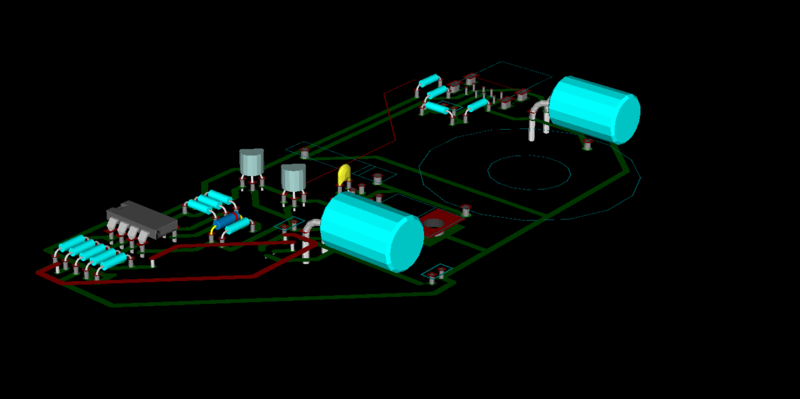
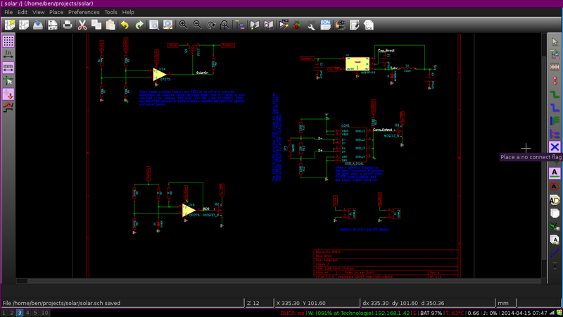
 The first etch wasn't a complete waste of copper, though. I found that my inductor footprint was twice the size it should have been (diameter != radius) and that the regulator's feedback was mistakenly connected to the switching supply, rather than the stabilized voltage by the capacitor. With that in mind, I trashed my original revision of the printed board and drafted one half the size. (The original had a lot of empty space.) I'm going to try etching again later today.


