By Ben Nitkin on
This is a continuation of my work with a solar-powered USB charger. See the last article here.
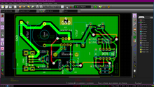
A few days ago, I tried etching the board. It's nearly the first time I've etched anything at home, and it didn't quite work. (Etching, FYI, is the process of masking a copper board, dissolving the exposed copper with a reactive salt, and then removing the mask to reveal a printed circuit board.) Although the traces were beautiful, the entire board was mirrored vertically.
 The first etch wasn't a complete waste of copper, though. I found that my inductor footprint was twice the size it should have been (diameter != radius) and that the regulator's feedback was mistakenly connected to the switching supply, rather than the stabilized voltage by the capacitor. With that in mind, I trashed my original revision of the printed board and drafted one half the size. (The original had a lot of empty space.) I'm going to try etching again later today.
Since you're still here, lets talk about some of the protection circuitry.
Reverse Discharge Protection
In sunlight, the solar panel voltage tends to about 10-11 volts. In the dark, it falls to 5V or less. The battery pack's operating range is between 9 and 10.5 volts. And therein lies the problem. When solar voltage exceeds battery voltage, everything's golden. About 150mA of power flow into the batteries, providing a relatively constant-current charge. The solar is incapable of charging the batteries above 11V, so damage is unlikely in the positive direction.
Darkness, though, provides a problem. In reverse, the solar panel looks just like a diode. As long as its voltage is within a few volts of the battery, no current flows. At around -3 volts, though, the solar panel begins to conduct a few milliamps backwards, draining the batteries. The darker it is, the more power conducts (up to a maximum of 12mA with full batteries and dark panels). This reverse current will drain the batteries and waste carefully collected power.
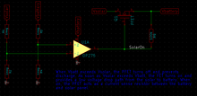
 This little circuit is my answer. The battery and solar voltages are each divided by two (the comparator can't compare voltages within 2V of its supply rail, which is the battery voltage). If the battery voltage is lower than the solar, the output goes low, which turns on the PFET. With the PFET on, the comparison transitions from a voltage to a current comparison: the difference in battery and solar voltage is entirely due to the voltage drop caused by the PFET. My particular PFET has a Rds = 0.2Ω, which implies a 30mV drop at full current. If the solar voltage drops below the battery voltage, current will begin to flow the other way, and the comparator will turn off the PFET. Twelve milliamps, saved.
Power on Demand
I've taken to calling this feature pod. I'm not sure if that's a real thing or not, but peapods are cool. Anyways...
The voltage regulator I'm using has an on/off input. Grounding the input shuts off the unit. Under no load, the unit consumes 4mA when turned on (just to run the internal switches, comparisons, and such). Powered off, it uses less than 200µA. To save power, I want to power down when the USB isn't used.
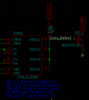
 Now, the USB specification states that the shell and ground pin should be connected. I'm violating that on my end, and hoping the other side conforms to the spec. On my end, the shell is connected to battery power through a giant resistor. When something's plugged in, it should pull the shell down to ground. The voltage on Conn_Detect, then, is 9V with nothing attached and 0V when something's plugged in. The NFET shorts the on/off pin to ground in the former case and provides an open circuit in the latter. Four milliamps, saved.
Brownout Detect
The final piece of protection circuitry is the most complicated. I'd like to force the regulator to powerdown when the batteries are depleted. Trouble is, the terminal voltage of a battery (the voltage at the terminals) has little correlation with the battery's state of charge. I was planning to compare a divided version of the battery voltage to a reference, but the battery voltage fluctuates with load: removing the load will allow the terminal voltage to increase, and then the regulator will turn on again and...
Shy of that, I'm not really sure how to measure state of charge. The unloaded terminal voltage is a useful metric, but I can't find unloaded voltage without shutting off the regulator. That leaves me at an impasse.
Construction Notes
Earlier this week, John and I committed the board to copper-clad. All the components are on now, and a few bugs came up. Here they are, with solutions:
- Low resistance in the battery-solar PFET (0.05Ω) led to difficulty detecting current direction. The TS372's offset voltage of 2mV far exceeded the sense resistors voltage drop. A 1Ω resistor in series with the PFET increased the sense voltage by a factor of 20.
- Incorrect footprint for the powersave NFETs (Gate-Source-Drain instead of Source-Gate-Drain). Fixed the footprint in KiCAD for the next version.
- Failing 2N7000 NFETs. Still diagnosing the cause, but I suspect that when one of the two transistors breaks, the other is fried. Replacing both at once may help.