By Ben Nitkin on
You probably know I'm working on building an autonomous robot as a senior project by now. (Psst. If not, read about it. Here.)
Now, this robot is driven by a pair of horsepower motors. Given full throttle, it'll easily hit 30mph. Even with safeties baked into the autonav code and Arduino motor driver, we need emergency stops. In fact, we have three. One's implemented in the packet radio: we've defined a code that will immediately kill the robot. A button on the robot will cut power to the main relay. The third E-Stop is a hardware radio E-Stop. That's the most interesting one, and I'm going to talk a bit about how it's designed. And since you're such great listeners, you'll listen. Thanks!
The radio E-Stop comes has a few requirements. I'm going to put them in a list, since I just realized that breaking up text makes it easier to read. It must:
- not use any software (microcontrollers are presumably banned).
- have a range exceeding 100'.
- bring the robot to a "quick and complete stop".
- be held by the judges during competition.
Okay. The last 'requirement' isn't technical, but it requires the E-Stop to be portable.
Given those requirements, I started putting together details about the e-stop. It needed a radio good to 100', so I found a cheap transmitter/receiver pair on Sparkfun. They're friendly in that they're easy to use, but that suggests a problem: what if someone else at the competition uses the same radio? We clearly needed some way to distinguish our E-stop from potential random noise. But it can't be too complicated; we're on a deadline and can't use software to distinguish long patterns.
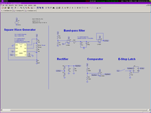
 My first thought was to listen for a sinusoid at a known frequency. Well, a square wave, really. They look similar to analog filters. Initially, the design called for an LRC resonator to pass the magic frequency and heavily attenuate others. The resulting voltage would be run through an envelope detector, then compared to a fixed reference; if the input exceeded the reference, the E-Stop would fire.
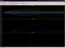
 In simulation, the filter worked fine. Most input frequencies were heavily damped, but the LRC resonated about frequencies within ~50Hz of the target. In a real-world situation, this circuit would ignore random noise, including brief hits on the magic frequency. The matched transmitter would sustain the magic frequency long enough to kill the robot.
The filter worked in simulation, but a professor warned that a real inductor would have real resistance (not just reactance (imaginary resistance (nested parenthesis))). That resistance would sap power from the resonant tank and reduce gain at resonant frequencies.
Instead, he suggested using a pair of tuned resonators: one on the transmitter and one on the receiver. The receiver could compare the incoming signal with the onboard one. If the frequencies were close, the signal would pass; otherwise not.
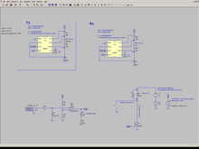
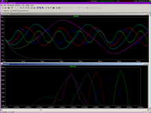
 My implementation used a pair of 555 timers to generate the frequencies as a pair of square waves. A variable resistor allowed for frequency adjustment. From there, the local receiver is compared to the receiver's radio input in an XOR gate. XOR (exclusive-or) is true when one input is true (not two, and not zero). When the square waves are 180° out of phase, the gate outputs 5V. In phase gives 0V. In between, the average output voltage fluctuates.
 The average is provided by a low-pass filter with a 3dB frequency of 50Hz. (An input at the 3dB frequency comes out with half its original magnitude.) When the input frequency is within ~30Hz of the receiver's resonator, a strong wave passes. Random noise registers very little response from the filter.
The output from the filter is compared to an adjustable reference voltage: when the filter voltage exceeds the reference, output power shuts off.
From there, it's just a hop, skip, and a jump to shutting down the robot. Normally, the circuit outputs 5 volts, which powers a 3A relay, which drives a 100A relay, which drives the robot's main power. When the E-Stop kills its 5v output, the solid state relay shuts off, then the main relay powers down, then the robot loses power. As power vanishes, the E-Stop itself shuts off, never to resurrect the robot.