By Ben Nitkin on
One of the most important sensors on the robot is a depth sensor, used to pick out obstacles blocking the robot. If the obstacles were uniform, color and pattern matching would suffice, but they're massively varied. The course includes garbage cans (tall, round, green or gray), traffic cones (short, cone, orange), construction barrels (tall, cylindrical, orange), and sawhorses (they look different from every side). Sophisticated computer vision could pick them out, but a depth sensor can easily separate foreground and background.
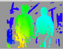
Most teams use LIDAR. These expensive sensors send a ping of light and time the echo. Time is converted to distance, and the ping is swept 180 degrees around the robot. We can't afford LIDAR. Our depth-sensing solution is divergence mapping. The sensing works in much the same way as a human eye: two cameras, a small distance apart, capture images synchronously. The images are compared, and their small differences are used to find depth. People do it subconsciously; the computer searches for keypoints (features that it can identify between frames). The matching fails on uniform surfaces, but works well on textured ones. (Like grass; isn't that convenient?)
 The depthmap can only be generated when the images match closely. That means that the cameras need to be fixed relative to each other, and the images need to be taken simultaneously.
We chose the PS3 Eye webcam because it's one of a few consumer webcams that can be synchronized. The sensor it uses includes two special pins, FSIN and VSYNC, that most chips don't expose. A positive pulse on the FSIN pin forces the chip to capture an image. As it begins the capture, VSYNC goes high for a pulse. Online, we found a few people who'd managed to synchronize the cameras by connecting the VSYNC pin of a master camera to the FSIN pin on slaves.
Actually connecting them took work. Getting the cameras open required a good bit of prying, and once they were open, we needed to identify where FSIN and VSYNC could be reached. The forums were helpful on that count. A bit of scraping revealed tiny solderable pads, and after some very careful work, I attached a small wire to both camera's VSYNC's, and one's FSIN. (VSYNC provides useful output to probe; FSIN is only for synchronizing the camera.)
The first time I tried, I baked one of the cameras with the soldering iron. The second time was more worky - an oscilloscope capture verified that the cameras were, in fact, synchronized!
Whereas divergence mapping failed when the unsynchronized cameras moved, the algorithm worked well for rapidly moving synchronized cameras - victory!