By Ben Nitkin on
Mark II sounds technical. So is this post. In the last post, I described how divergence mapping works. Fundamentally, divergence mapping creates a 3d image using two cameras, much like the human eye. The link above goes into more detail on our high-level method; this post is about hardware.
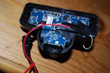
Here, you'll learn how to modify a PS3 eye for synchronized images. (Apologies, but I'm shy on pictures of the camera coming apart.)
First, remove all of the screws from the camera's backside. They're all hidden under the round rubber pads, which will pry off with a slotted screwdriver. The screws themselves are all Phillips.
Next, gently pry the back off of the camera. The board and lens are attached to the front piece of plastic; the back will pull off. The two sides are attached with plastic hooks. I found that needling a slotted screwdriver between the layers of plastic and then twisting worked well. Start at the top, and save the round bottom for last (it's tough to get open).
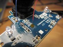
 With the camera open, find the VSYNC and FSIN pins. FSIN is the top pad of R26 (an unpopulated resistor). VSYNC is harder to get at. It's moved in recent versions of the camera; on ours, it was exposed in a via. (A via is a place where a printed trace is moved between layers of the board. It's a metal-plated hole drilled through the PCB.) After scraping off soldermask, you can attach a wire to the via with very careful soldering. Very careful soldering is a prerequisite for this whole affair, actually. These traces are tiny!
Once FSIN and VSYNC are exposed and have wires attached, bring them out. Make sure to add some strain relief, too. I caught the wire under a few screws to keep the solder joint safe.
As previously mentioned, VSYNC is a start-of-frame indication, and FSIN is a trigger input. We used two cameras, and slaved them to each other. (Ground was left disconnected on the assumption that USB enforces a common ground.) Others have used an Arduino to generate the pulses. If desired, multiple cameras could be slaved to one master, too. No matter how it's set up, the FSIN pins of the slave(s) are attached to a master VSYNC. I'm not sure how much sway the FSIN pin has:
- If it's held low, does the camera return to 30fps operation?
- If pulses are erratic, will the camera reliably match FSIN?
- Does the computer notice any change in framing times when the cameras are slaved?
My goal was just to synchronize the cameras, and I did. The only downside I've noticed is a 1px horizontal yellow line that appears on the slave camera. My best guess is it's interference from the falling edge of VSYNC, but I don't know. Oscilloscope traces verify the camera works, and that's enough.
Speaking of which, I made a video! If the embed isn't working, see vimeo.com/bnitkin/ps3sync