By Ben Nitkin on
Last year, Helen, Haley & I (we call ourselves the Technology LLC when we're trying to sound official) volunteered at the local elementary school with SWE. They worked with the entire 4th grade class. After dividing children into groups of 4-6, each one recieved some flavor of an Agilent educational kit. For simplicity, we only used three kinds: a solar-powered car, an electronic matching game, and ... something else. It's not important.
All of the directions were terrible. They read like a hybrid of a textbook and IKEA furniture directions. For the matching game, there was a single picture with parts labelled A-H, and cryptic text-based directions. The kits also cost $5-$8 per student. As we left, the three of us offered to provide a similar experience with reduced terrible-ness.
 After some brainstorming, we decided on LED flashlights. Depending on the audience, we could talk about resistance, ohm's law, systems of equations, color wheels, the difference in additive and subtractive palates, and lots of other fun stuff. Additionally, flashlights would be inexpensive and easy to mass-produce. RGB LED's provided a little extra whiz-bang.
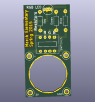
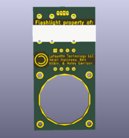
 The simple flashlight I created allowed children to enable or disable each of the three colors, provided a master on/off, and let them easily swap resistors to change the brightness of individual colors. The single-sided PCB was easy to design and allowed them to trace the copper powering their circuit. For kicks, the backside of the flashlight included a spot for their name. A coin cell fit into the large cutout, ensuring a slim design.
I ordered the PCBs from Advanced Circuits. Since they offer a flat rate on anything up to 60 square inches, the flashlights were panelized before submission. Other fabrication houses, like OSHPark or Dirty Cheap Dirty Boards, charge by the inch. In that case, a non-panelized version is easier. The linked files are zipped Gerbers, which is a bizarro format used by the machines that etch PCBs. I also ordered parts and an oddball selection of resistors form Digikey. Here's the BOM with part numbers. Each flashlight requires one of each of the following components:
- Quad DIP Switch (450-1781-ND)
- RGB LED (754-1615-ND)
- CR2032 Battery (P189-ND)
I ran some quick math to decide on resistor values. The LED's datasheet says that forward voltage (voltage at which the diode passes 20mA) varies by color: red is 1.9 volts, while green and blue are 3.3 volts. The datasheet doesn't say so, but 20mA is a lot. Like, blindingly bright. To tone things down a little, I found forward voltages for 5mA from I-V tables in the datasheet. Red drops to 1.8 volts, blue falls to 2.8, and green is a smidgeon shy of 3. The difference in the 3V battery and the forward voltage is consumed by a resistor, governed by ohm's law: voltage is resistance times current. For red, (3-1.8) volts = x ohms * 5mA; x = 240 ohms. For blue, (3-2.8) volts / 5mA = 40 ohms. And for green, a zero ohm resistor should allow 5mA to pass.
Working from those ballpark figures, I elected to buy a range of resistors from 0-1200 ohms to allow for a wide range of currents. Some set of those resistors will yield equal brightness; others will differ. All resistors are in 1/4 watt, through-hole packages. These. I used the following resistances:
- 0 ohms (a jumper)
- 47 ohm
- 120 ohm
- 200 ohm
- 240 ohm
- 300 ohm
- 510 ohm
- 1.2 kohm (1200 ohm)
Resistors are labeled using a 4-band color code. Frankly, it's not too useful to know, but giving kids a color key helped them immensely. We handed out a sheet that spelled out each color combination (Red-black-black-gold) and the value (50). Digikey has an article on the color codes, as does Wikipedia and any number of other sites. I won't go into it here.
Prior to visiting the fourth graders, we assembled the flashlights and created a basic worksheet to accompany the flashlight that discussed colors, ohm's law, and other principles. Flashlight assembly was fairly simple: the LED and DIP switches were soldered in place and two wires were installed to retain the battery. One ran diagonally across the top; the other went the other way across the bottom. Slipping the battery between the diagonal wires provided power.
Classes themselves were quite fun. For three fridays, the three of us headed down to the school and each spoke for a few minutes. I handled the circuitry aspect, Haley spoke about colors, and Helen tried to make everything make sense to the non-engineers in the room. After boring the 4th graders for a while, we handed everyone a flashlight and a single resistor. Some of the classes got assembly instructions immediately; others were left to experiment. We sort of iterated between asking them guided questions and handing out additional materials.
Mostly, we tried to teach that resistors controlled brightness (current flow) and that circuits were made of continous loops of wire. The flashing LEDs were big hits.
As the lesson wound down, we offered to take the flashlights back to solder some set of resistors down. Some children took the offer; others chose to keep playing with resistors. We soldered things up on campus and brought them back the next Friday.
I wrote a lot here. Hopefully it's at least a little useful to someone. But it's too long now, so this is all. Thanks for reading! And as always, if you have any questions, email me! There's a contact link at the top of the page.