By Ben Nitkin on
Yesterday, I went for a walk. Getting outside is always relaxing, and the town was beautiful in the dark, decked out for Christmas.
I also saw a broken electric radiator curbside. At least I hoped it was broken. On the way back home, I found the house again, hefted the thing onto my shoulder, and carried it a mile home. (I set it down too hard when I arrived and broke two of the casters. Now it was definitely broken.)
Hopeful, I plugged it into the wall, turned it on, and... nothing! Hooray! I had an excuse to take it apart. (The heater, by the way, is supposed to retail for $80. It's also got bad reviews, but hey. Free.)
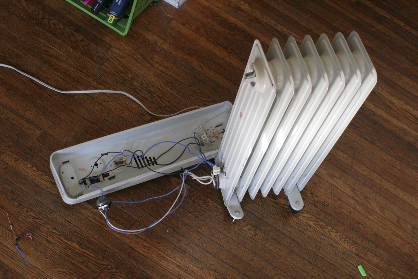 The front came off with a few screws, one behind the handle, and two more at the base. The guts contained a four-pole, four position switch, a thermostat, a fuse, two lights (power and caution), and a ton of wires.
I started debugging with the switch. It had four wires going in, labelled L, 1, 2, & 3. The four positions were, naturally, Off, Low, Medium, and High. You see these switches everywhere - toaster ovens, heaters, all sorts of simple appliances. In this switch, L was 120VAC power, 1 was the power light, 2 was the low-power coil, and 3 was the high-power coil. 1 and L were connected in every mode but Off. 2 and L had continuity in Low and High. L energized 3 in the medium and high settings. In each setting, a different combination of heating elements provided a different output heat.
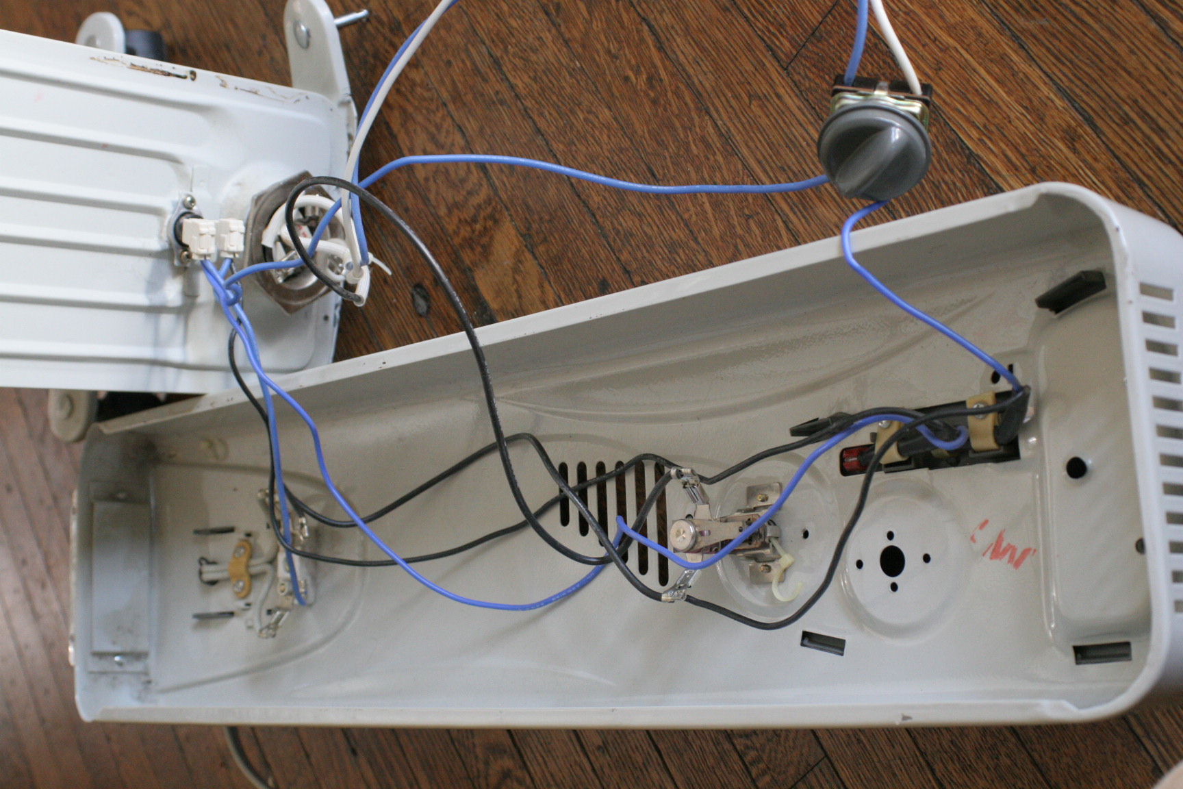 Moving along, I briefly probed the thermostat. True to form, it switched based on temperature and had very low impedance when on. The fuse, too, provided a short circuit. The heater coils had their grounds shorted together; one coil measured 15Ω, and the other was about 23Ω. All of the visible components behaved as expected.
With basic debugging fruitless, I decided to energize the heater and watch voltage flow. (And before you get all antsy about mains voltage, I know what I'm doing, and I didn't hurt myself.) As expected, there was 125VAC across the wire entering the heater. That voltage passed the fuse, then dropped to 3VAC before reaching the power switch. The wire between them, I noticed, was covered in shrinkwrap. My first guess was a failed junction.
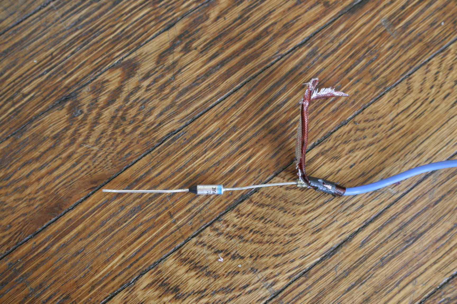 Out came the knife. Under the shrinkwrap was a layer of tape, and under that was a spaceship. It sure looked like one, at least. It's marked D125PNUE - D and PN both hint at a diode. The multimeter reported no continuity in the diode testing mode. Either its threshold voltage is too high to detect or it just burned out. I guessed the second, took it out of the circuit, and plugged the remaining wire back into the main switch.
Voila! It worked!
If you're freaking out about tearing a part out, here's my explanation. A diode allows current to pass one way, but not the other. In a circuit like this, it forms a half-wave rectifier, clipping negative voltages but passing positive ones. For an ohmic load like a heating coil (where V=IR applies), clipping half of the input voltage will clip half of the input power. The heater would draw current for half of every 60Hz cycle.
Now, the heater claims to output 1.5kW of power. By ohm's law, Voltage2/Resistance = Power. Given 125VAC (RMS) and that the heating coils have a parallel resistance of 9.1Ω, the heater will consume 1580 watts. Slightly above the 1.5kW specified, but reasonable. As mentioned above, by halving the heater's duty cycle, the removed diode would have limited power to about 0.8kW.
With its repairs, the heater works again. Now to replace the broken casters!
12/23 Correction: The component removed was a 128°C thermal fuse. The heater has a second thermal breaker in the base, so it should still be protected from overheating. That said, radiant heaters have a bad reputation for overheating, so this one will not be used unattended.