By Ben Nitkin on
In ECE211 (that's Digital Circuits I, for those of you who don't go to Lafayette), we've been working with digital circuits. Surprising, right?
I was frustrated that I needed to draw out these complicated circuits by hand, and that the paper never gave me any helpful feedback. So I decided to write a logic gate simulator, using my favorite language for graphics, Processing.
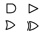
I've just finished the alpha version. It isn't functional yet, but there's finally a bit of a GUI. The program simulates simple logic gates (and's, or's, xor's, and inverters), which are connected with wires. There are also input and output blocks to show final logic states.
The circuit will be simulated from the inputs towards the outputs. Whenever a gate is changed, it informs all wires on its output terminal of the change. They inform the gates that they are connected to, and the new values propogate. I'm not quite sure how to handle circuits with feedback yet, though. I could set up a clock to step through each phase change, or I could let the program flip out as states fly back and forth.
But I'm getting ahead of myself. At the moment, I have reasonably complete definitions for the gates, and have just written a basic UI to place and move gates around.
When I find more free time (Mommy? What's free time?), I'll add more functionality. For now, enjoy the preview!
