By Ben Nitkin on
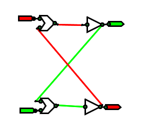
This weekend, I decided to throw out my previous logic simulator and make a new one based on what I'd learned. It's still in beta, but I got it to simulate an SR latch, and I'm proud. I'm going to sleep now, but wanted to tell the world about my success. Latches are awesome.
Reading this diagram: Red is false, green is true. The triangles are inverters; the blazes are OR gates (I'll pretty them up later). The flags on the right are inputs; the flags on the left are outputs. The green circles are inputs and outputs - the points where gates associate with each other. They're only shown for debugging.
More later. I promise.
